Value Range for Aircraft Transmitters
1. Receiver outputs a PWM signal (one PWM corresponds to one channel)
The transmitter of the aircraft wirelessly transmits a signal to the receiver. The receiver is connected to the servo, motor, and other devices. One device connects to one channel of the receiver, and there are three lines of each channel, including signal, positive pole, and negative pole. The signal is PWM (pulse width module). For specific products, please refer to https: //www.radiolink.com.cn/r7fg
(1) The receiver outputs a PWM signal

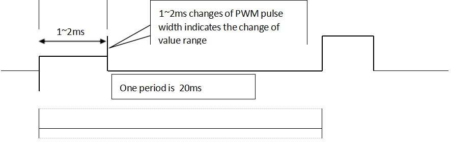
(2) PWM Range
The above chart shows that a PWM signal changes between 1 and 2ms (ms: milliseconds), which is a change in the value of a channel. 1ms is called the small value, 2ms is the large value, and 1.5ms is the midpoint. The value can be described in microseconds (us) in addition to milliseconds. 1~2ms corresponds to 1000~2000us. When the value is described in microseconds, the “us” is often omitted. For example, we use the midpoint 1500 instead of 1500us.
(3) Channel Value
The channel value is the PWM value. The small value is 1000, the midpoint is 1500, and the large value is 2000. The value of the transmitter in Mission Planner of Betaflight and PIXHAWK is represented by the PWM value.
2. The channel value in the transmitter.
(1) The value of joysticks. Joystick DOWN and RIGHT are the large values.

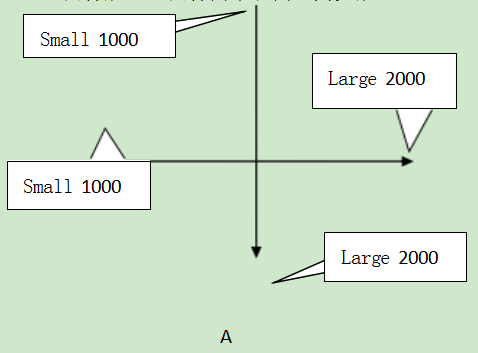
A: Joystick DOWN and RIGHT are the large values. (Applies to Futaba/RadioLink transmitter)

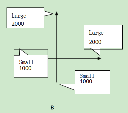
B: Joystick UP and RIGHT are the large values.
(2) Servo display and value in the transmitter

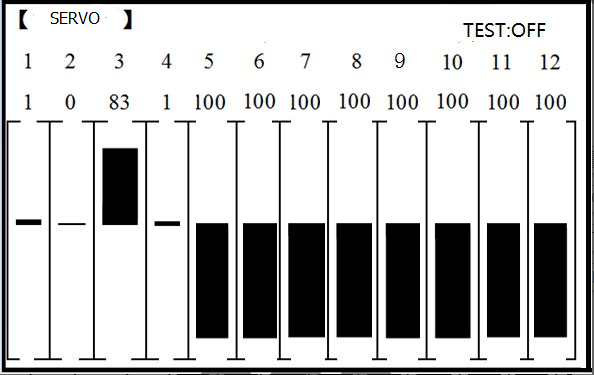
The above picture is the display of the value of RadioLink transmitters.
The upper one is a small value, and the lower is a large value.
(3) The value of switches/knobs
Switches: Switches DOWN or INWARD are the large value. Switch UP or OUTWARD are the small values.
Knobs: Clockwise is the large value. Counterclockwise is the small value.